
The Hull
The hull shown here has details for the USS Oklahoma City CLG-5 as of about 1971. It is basically the original Cleveland class hull launched in 1944, with very few modifications below the waterline. Above the waterline on the hull and main deck many details shown were added during the CLG conversion in 1959.

The hull was quite a challenge because there are few flat surfaces. I had to stretch the skin over 150 lines that represented the frames of the hull. The initial model had just a simple smooth surface for the hull, and it served to help me place other features. But the real hull was plated with overlapping sheets that are quite visible in the photos, and it had many hull openings and other small details.
The plated hull model was a six month project. The shell plating had about 480 individual plates in 15 strakes (rows of plates). Five strakes at the bow were arranged vertically and the remaining were horizontal. Plating overlap was complex, with some plates overlapping their neighbors in and out above and below, some overlapping the lower strakes clinker style, and some strakes butt welded together edge to edge. In this drawing individual plates within a strake are shown in alternating dark and light tones of the same color. Port and starboard sides were mostly the same except for positions of hull openings. However, the garboard (A) strake (red) just outboard of the keel (green) and half siding (blue) had a slightly different plate arrangement port and starboard so plate edges did not align on opposite sides of the keel. Click on the picture to examine the plating in greater detail.
Steel plate is measured by weight, in pounds per square foot - for example 1" thick plating weighed 40.8 pounds per square foot, and was marked 40#. The shell plating varied in thickness, generally heavier amidships and lighter at the bow and stern. Heavier plating was used where water pressure was greatest and where greater mechanical strength was needed. Plating was thinner at the main deck level (sheer strake) and thicker at the keel. The sheer strake plate at the main deck level was 10# (1/4" thick) at the bow and stern, and 35# (7/8") amidships. Plating at the bow varied from 10# (1/4") at the main deck to 30# (3/4") at the bulbous part just above the keel. The keel plating ranged from 37.5# (15/16") at the bow to 68# (1 2/3") amidships.
Prior to WWII most metal hulled ships were riveted. It was thought that welded seams were not as strong as rivets. During the war production was rushed as much as possible. Much of the forward and after parts of the Cleveland class hulls were welded. The midships sections were still riveted. Seams between hull plates were reinforced with backing plates. The upper parts of the hull had vertical backing plates on the outside over the seams and horizontal backing plates inside the shell. Below the waterline all backing plates were inside the shell plating to reduce drag.


The hull had a great number of openings. All of the deck drains (scuppers) drained through pipes to openings a few feet below the upper edge of the hull. Each water tight hull section had overboard discharge fittings for 2 1/2" fire hoses. These were simple holes cut into the shell plating with the fire hose fittings welded inside. If a compartment flooded and had to be dewatered portable pumps were used and the discharge was connected to these ports using ordinary fire hoses.


The plumbing drains from showers and toilets discharged above the boot topping (the broad black band at the water line). During WWII these drains dumped straight overboard. For the CLG conversions these were enclosed in "split pipe" drain covers to prevent waste from spraying out onto docks or nearby boats. Loops of pipe were welded to the hull to protect the drain covers. These drain covers were a bit of a problem - photos show as many as 24 and as few as 14 along the starboard side, and a few more on the port side. No two photos show the same number! Apparently they were frequently torn off the sides of the ship in heavy weather and had to be replaced in port. Furthermore, they were not always replaced with the same design. What you see here is a possible configuration for the 1971 period, but the ship may never have had exactly this arrangement!
The top of the black boot topping was below the top edge of the armor belt on the original Cleveland class ships. The CLGs were much heavier and floated lower in the water. The boot topping extended to the top of the armor (26'-2" ABL - Above Base Line) on some ships and higher on others. It was painted at various heights on the Oklahoma City, but in later years was painted up to the knuckle in the shell plating above the armor belt (27'-1 3/4" ABL). The bottom of the boot topping was at the knuckle in the armor belt on all ships 21'-9" ABL. The Draft Limit Load Line Marker was placed 25'-6" ABL.


Below the waterline the hull looked like Swiss cheese. Twelve 26" and 27" sea chests provided sea water intakes and discharges for the condensers and steam injectors. These large openings had flat bar gratings to keep large sea animals out. The middle three bars were "portable" - they could be removed to allow access. The smaller intakes had portable perforated plates but most discharge sea chests did not have gratings. There were at least 32 sea chests for the engineering spaces and a half a dozen more scattered along the underside of the hull. Many of the engineering space sea chests had steam fittings to allow flushing the openings to clear out debris and marine life.
The lower bow plating was bulbous, with a solid stem running from the keel to the top of the hull. An elaborate stem extension ran forward from the keel, with a donut-shaped bolster around a hole. Originally mine sweeping paravane cables ran through the hole. At the stern was a large opening for the stern lights. The white and blue stern lights were used for formation steaming. Below them was a conical Wake Light. The first two Cleveland class ships had these three lights attached to the outside of the stern plating. Later ships had the recessed hull opening to protect the lights from wave action.
Main Deck
The fittings on the main deck were mostly on the bow and stern. Forward were some vents, hatches and the anchor handling gear. Aft of the helo deck on the stern is another collection of vents, hatches and other details. There are still a lot of details to be added to the main deck. The area that was covered with 2 1/2" thick teak planking is shown in tan. Eventually I will model the individual planks. Life lines and life rails need to be added and the boat winch foundations must be added midships.
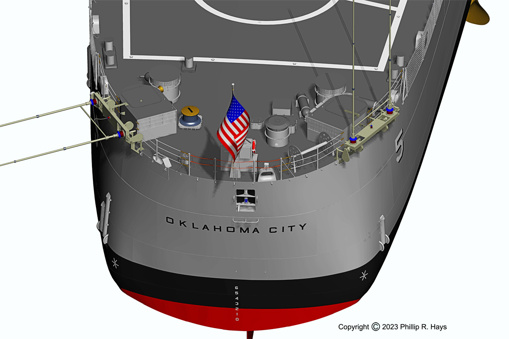
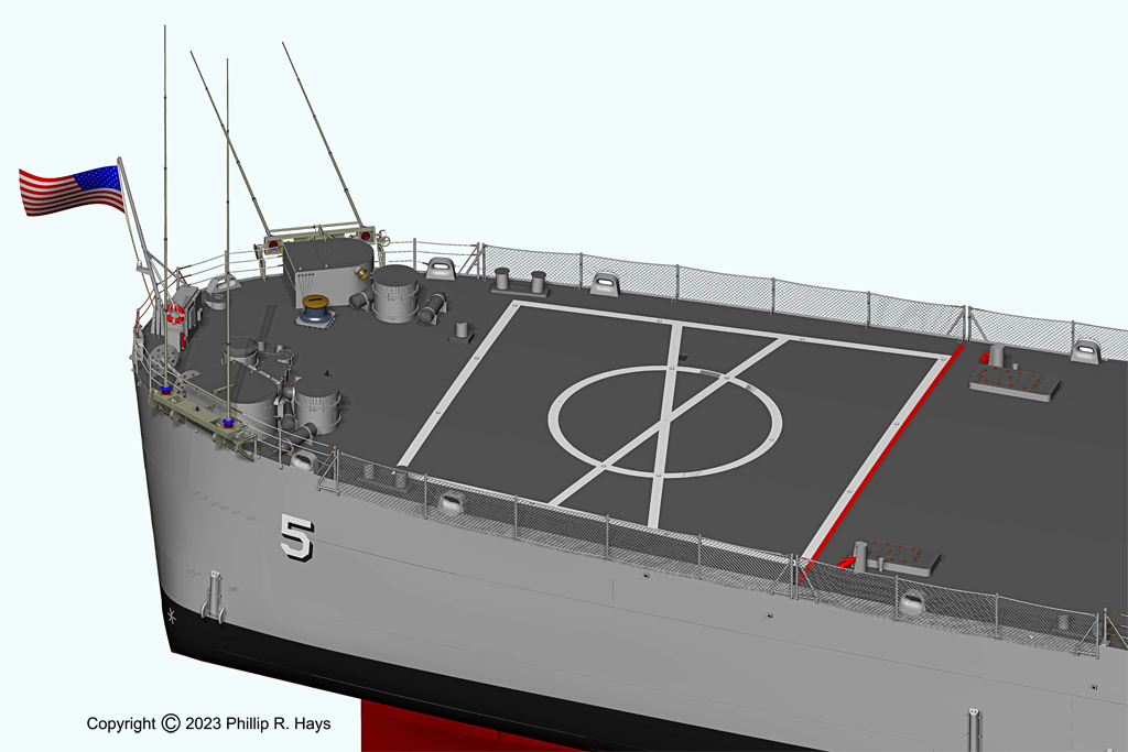
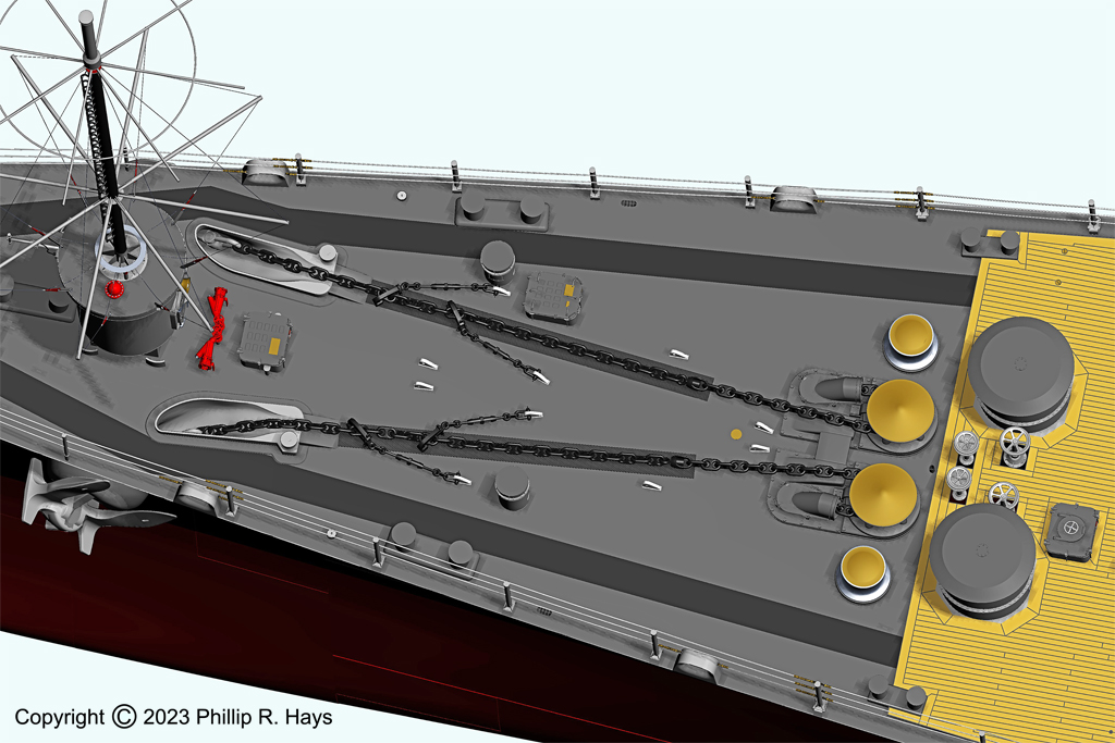
Only a few things on the main deck remained in the original Cleveland configuration after the CLG conversion. The anchor gear and capstans, and the control wheels just aft, were not changed. Many of the 14" bitts and 16" chocks are in their original Cleveland class positions, but some have been moved. The 10" bitts outboard of the capstans seem to be unique to the Oklahoma City and were added during the CLG conversion. The small bucket vents outboard the anchor chains were added after conversion - these originally were "gooseneck" vents like those still found on the USS Little Rock CG-4 museum ship. The two large and two medium sized bucket vents just aft of the anchor windlass and capstan control wheels are the original Cleveland configuration vents. All of the fittings on the fantail were added with the CLG conversion.
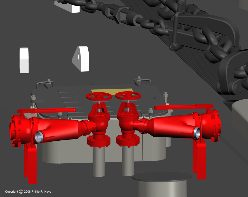
The anchors weighed 13,000 pounds (6 1/2 tons) and were lowered and raised with stud link chain that passed around the two anchor windlass "wildcat" sprockets. The chain ran on a chafing plate welded to the main deck. The chain was stored in chain lockers in the bottom of the hull. The ship carried 125 fathoms (750 feet, about 890 links) of anchor chain in the starboard chain locker and 170 fathoms (1020 feet, about 1200 links) in the port locker. The anchor chain was formed from 2 1/2" diameter wire. Each link was 15" long, weighed about 50 pounds, and was rated to carry a load greater than 250,000 pounds. Some of the chain links were "breakable" - they came apart to allow the chain to be separated into two parts at the breakable link. Two swivel lengths that relieved rotation stress can be seen at the aft end of the chafing plates near the wildcats. The anchor windlasses had brakes to hold the chain when the anchors were being lowered or raised, but at all other times the anchors and chains were held in place with "stoppers," the short lengths of smaller chain fastened to the deck, with pelican hooks at the ends. These hooks could be opened, slipped over the anchor chain and then closed to hold the chain in place. Two stoppers were attached to each chain. Each stopper had a turnbuckle to allow slack to be taken up so the chain was held securely before the windlass brake was released.

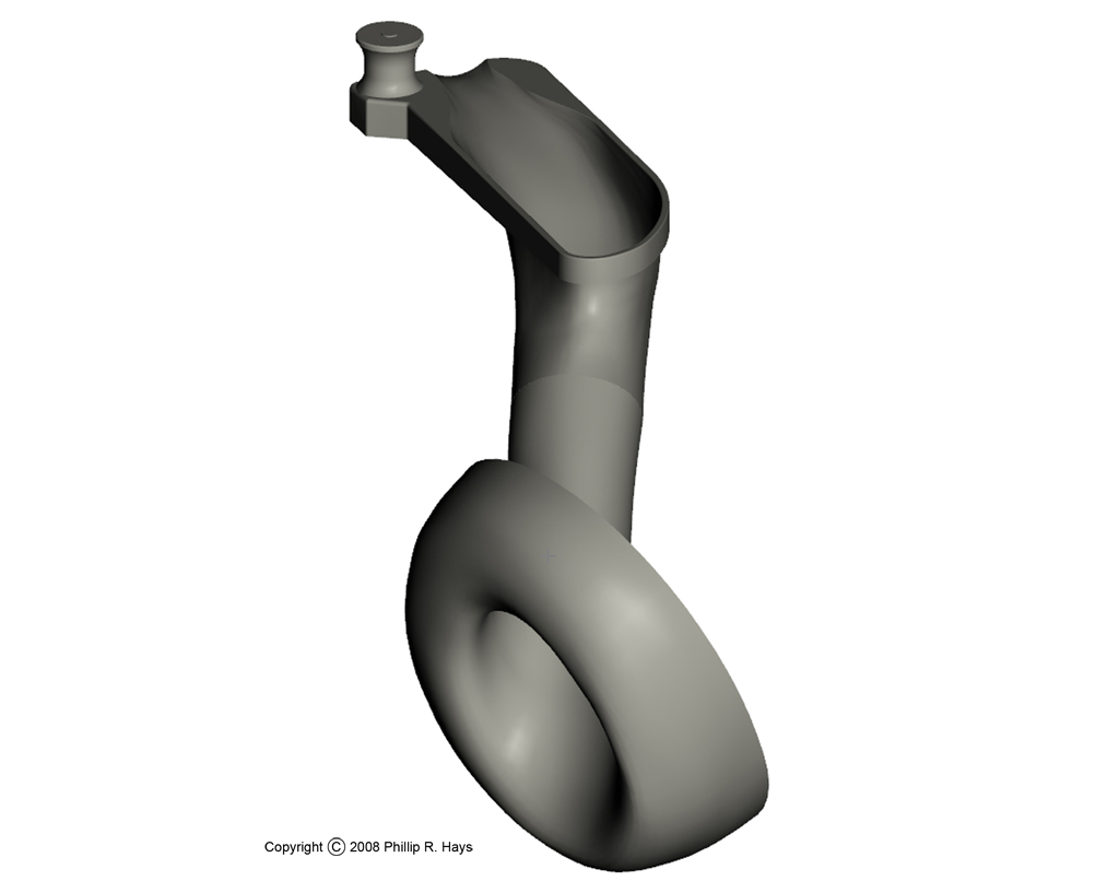
The bolster and hawse pipe for the anchor chain absorbed the weight and friction as the chain passed through the hull. The bagel-shaped bolster was drawn from a series of horizontal and vertical cross sections shown in the blueprints. This turned out to be the most difficult thing I have ever modeled. It took about a month of evenings and weekends. The anchors themselves did not "anchor" the ship in position, they just held the end of the anchor chain so it wouldn't slide across the bottom. It was primarily the weight of the anchor chain itself (more than 25 tons), and the drag of the chain on the bottom, that held the ship in position while anchored.